| A8274 B |

While keyboards have greatly simplified the man-electronics interface, their manufacture is a complicated process that relies heavily on quality control. The cost of quality control during keyboard production can easily be determined. Difficult to calculate is the cost of lost time, goodwill and good name due to the failure of finished products. For this reason, keyboard testing before final assembly is an essential step in membrane switch and other types of keyboard production.Various test methods for keyboards have been developed and modified in recent years. All have one thing in common: the keys must be activated. This may be in a particular order or in such a way that each key to be tested is pressed with the necessary force to operate correctly. Total test time is dependent on several criteria: number of functions and parameters to be tested and the speed of the handling system. The keys can be actuated by hand, key by key, with the test system evaluating the results. Alternatively, the keys can be actuated automatically using solenoids or pneumatic cylinders. There are several advantages in the latter: the cylinders can be closely spaced the pressure applied to the key can be varied simply and linearly by changing the air supply pressure and the exerted mechanical pressure is consistent over the whole stroke.
Keyboards are designed in a variety of different matrix combinations. This requires ‘teach-in’ systems with very comprehensive capabilities by which mismatched matrix combinations, common bus errors, shorts / open circuits, double release and electronic code errors can be traced. An important characteristic to test is bounce time, the time between the first potential change in the output of a switch and the last time the change occurs.
During that time, the switch releases a predetermined electronic switching level.Contact resistance is the resistance of the line to contact (ie. loop resistance encountered on pressing the key). The resistance of the connecting lines must be compensated for on keyboards using standard push button switches. Most membrane keyboards have such high resistance tracks that the resistance of the connection line is irrelevant.
Insulation resistance should be measured between every connection on the keyboard and, if applicable, the base plate. This is a very important test, particularly for the tracing of marginal faults. Used in a production process, the insulation test helps reduce production costs by tracing faults at an early stage. It is essential to perform specific insulation resistance measurements at high voltage levels.
The force / displacement characteristic gives an indication of the mechanical feel of a pressed key. Due to the variations caused by production tolerance, supposedly identical keyboards can vary considerably. The tester can plot the force / displacement curve of any key using sensors to measure both force and displacement. The system should be able to interface with an x-y recorder and mark the electrical make and break points at the correct position. The force / displacement test system can be enhanced by interfacing to a PC with menu driven software. The software should be capable of establishing tolerance windows and envelope curves.
Storing of test data is essential for statistic process control.Recent developments allow an x-y positioning table to be incorporated with the force / displacement test system. This allows you to test each key of every keyboard at its exact position (repeat accuracy). To fulfil the wide range of requirements imposed by the user, the test system must satisfy a number of demands. This is particularly important if the user has a large number of different keyboards that must be tested. Because modern electronic appliances have such a rapid turnover, automatic keyboard test equipment must be rapidly adaptable to a considerable number of different applications, including:
* Hand testing on small batches of individual keyboards where the speed of testingInterface capability to a PC allows for program storage and data acquisition. Life expectancy testing of individual keyboards is essential. The system should be able to periodically monitor the various functions and characteristics and store information for statistic process control.
rates is a low priority.
* Semi-auto test on moderate to large columns of products. Keyboards must be
pressed automatically at speed, using human finger substitutes.
* Full auto test on large quantities where the units under test are fed and sorted
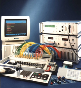
under the control of the test system.The design of the test system should be modular in its concept and adaptable to any number of different applications simply by changing or rearranging the modules. Each unit may be used on its own, or in combination with other test units. The system should have GPIB interface capability for programming and data acquisition via PC . Complicated functions and time critical testing are stored in an associated unit and carried out directly. The pneumatic system should also be of modular design. A variety of 1/0 modules should be combined in any order, depending on the test requirements. Using such a system, all forms of manipulation and operation can be simulated on the unit under test (UUT). The system must have interface capability to evaluate feedback signals and be able to check LEDS from the UUT.
Various actuators for linear and rotary operation, as well as universal frames for the free positioning of the actuators are vitally important. These should make the system rapidly adaptable for a considerable number of UUT’s, irrespective of their geometric form or size. The necessity to connect various forms and designs of electrical connectors on the keyboards under test to the test system has been solved by the UK2 universal connector system. Universal connectors must be easily adaptable for tag tails, pins, and edge connectors,
irrespective of the number of poles or position of the point to be connected. The frames should be easy to incorporate into an automatic handling system or flexible conveyor mechanism. Various I/0 cards in the test system should be used for the control, positioning and activation of the keyboards under test.Rights of changes reserved.